Lab 4
Introduction
For Lab 4, we were tasked with programming our MCU to play music by producing a square wave that was then sent to a GPIO pin. This was done using timers that dictated the state of the GPIO pin, which creates a square wave with the correct frequency and duration.
Design and Testing Methodology
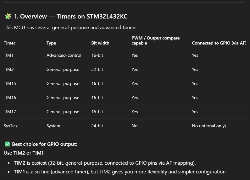
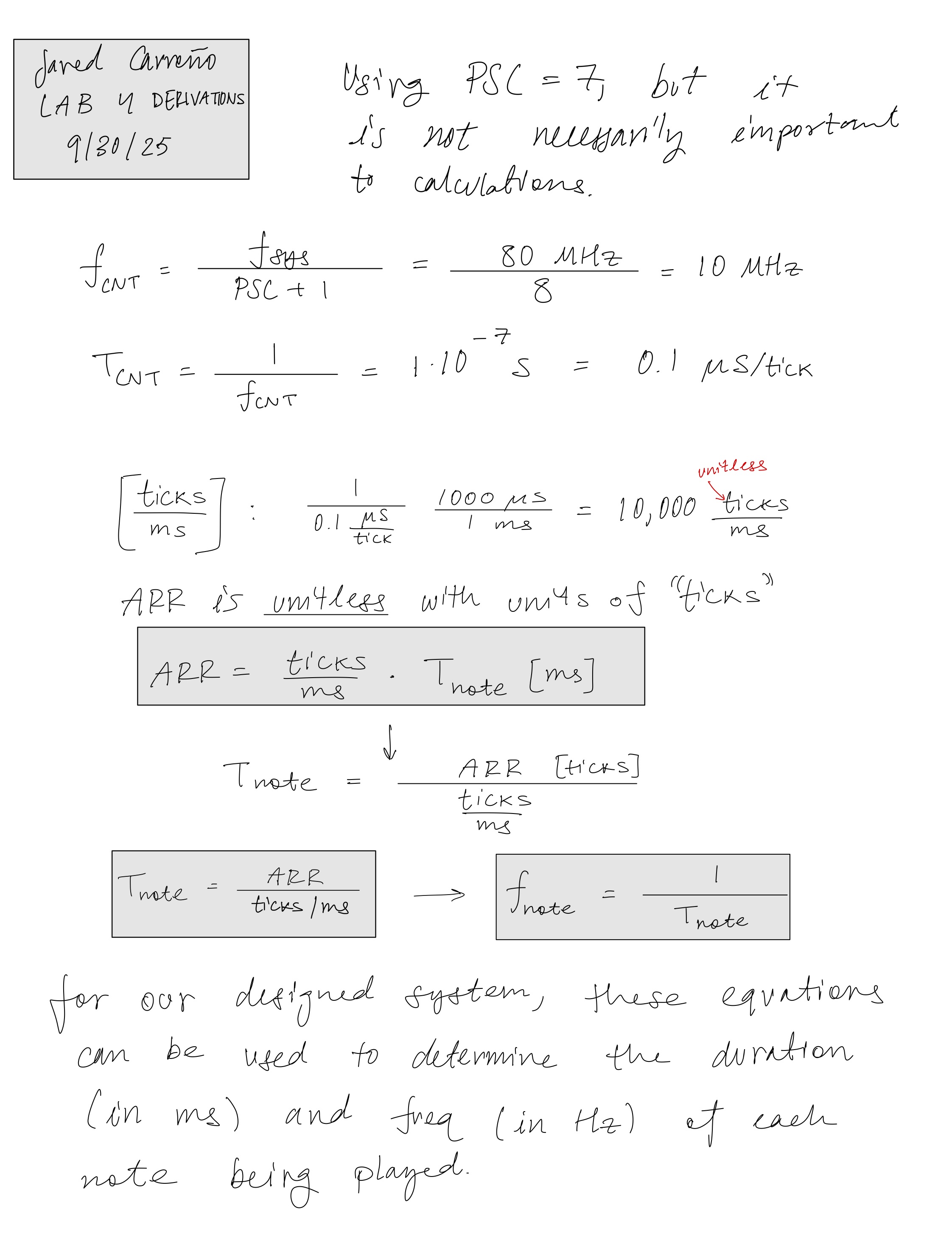
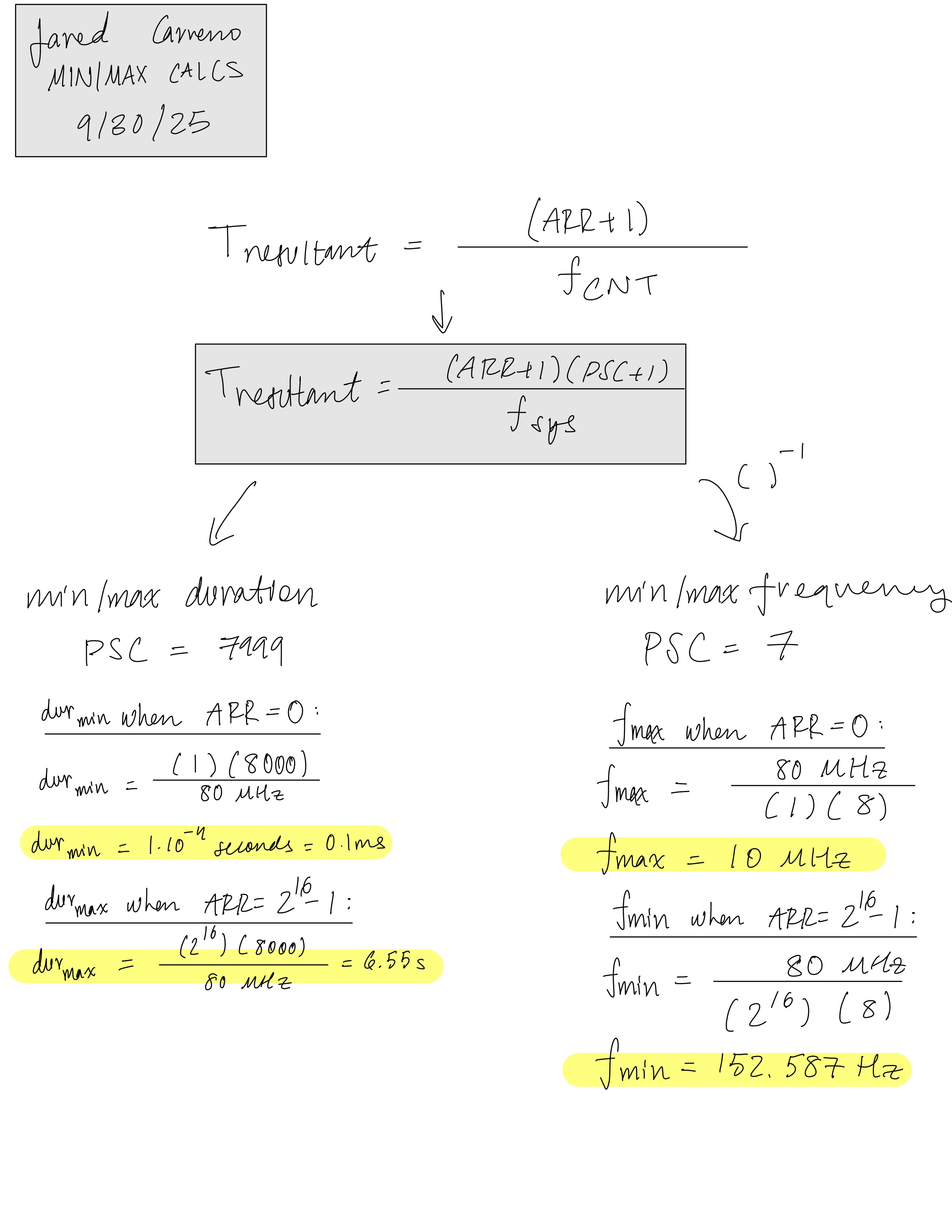
The design utilizes two timers, TIM15 and TIM16. These two timers have both a GPIO mode and PWM mode, which is what we want, but they also have the same registers, which will simplify the creation of our structs. The two timers start initially at the frequency of the system clock, fsys = 80 MHz, but are divided differently. The PWM timer has a PSC of 7, which allows for a precise measurement of the timing, while the duration timer has a PSC of 7999, which allows for higher frequency resolution. This can be seen by reducing the PSC for both and seeing the wrong frequencies being produced and/or the note duration being too short if the clock is too fast.
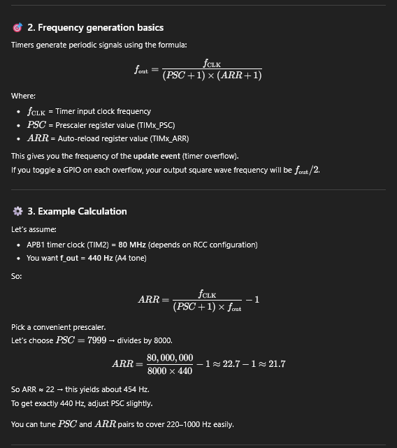
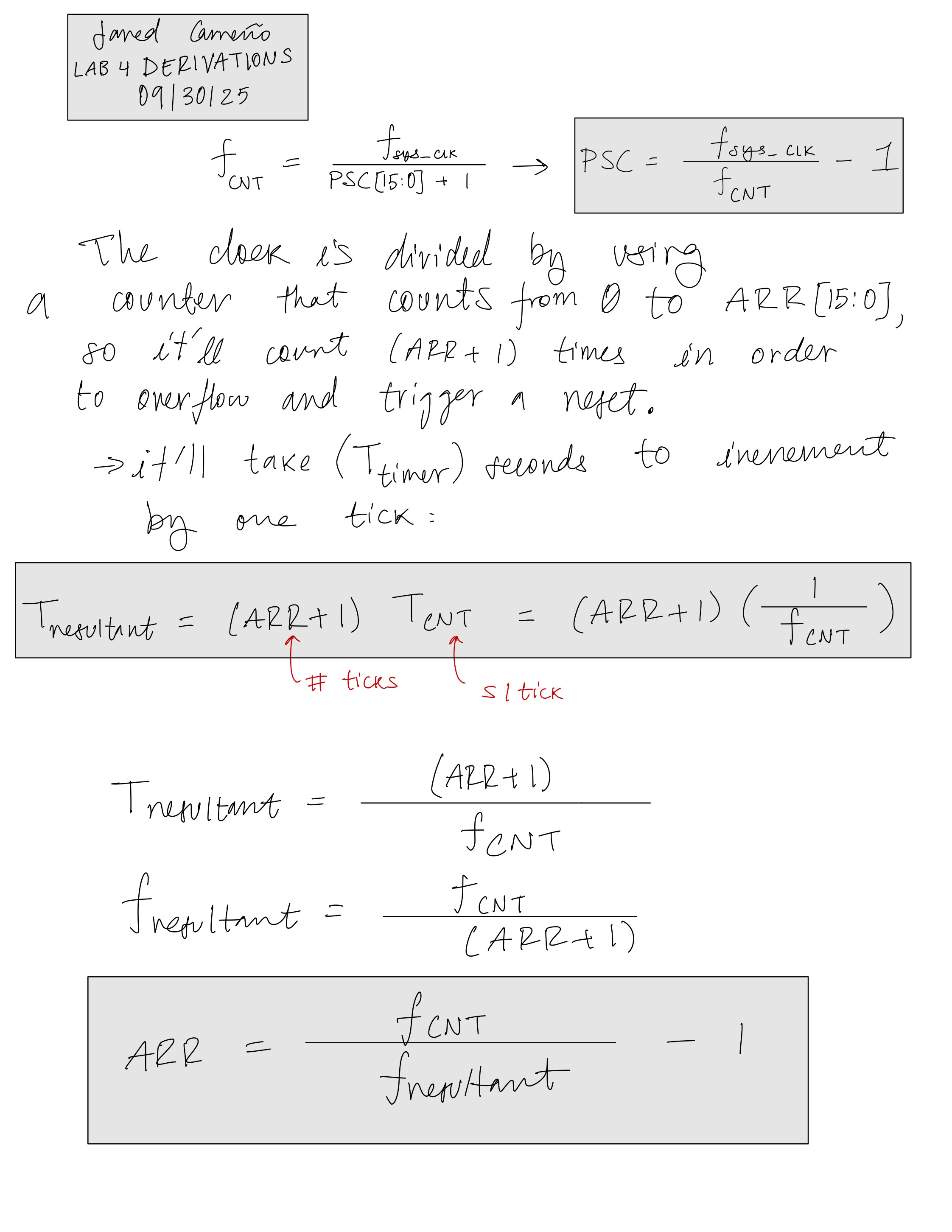
Using the equations shown in Figures 1 and 2, we took advantage of the ARR (auto-reload register) which sets a value at which we want the timer’s counters to stop and reset. The pulse will stay HIGH until the counter counts to the value of ARR. This can be changed using the CCR1 register, which is set to half of the ARR value, meaning that the wave is set LOW when the counter reaches half of the ARR value. This produces a wave with 50 percent duty-cycle.
Technical Documentation:
The Git repository containing the source code of this lab can be found here: Lab 4 Repo.
Derivations and Calculations
Figures 1 and 2 showcase derivation for equations that were used to determine ARR, as well as the period and the frequency of the note the system is outputting, Tnote and fnote. In Figure 3, we have the maximum/minimum frequency and duration calculations that provide justification as to why we decided to choose these prescaler PSC values. The reason why the PSC value is so important is mentioned in the Design and Testing Methodology section.
Schematic
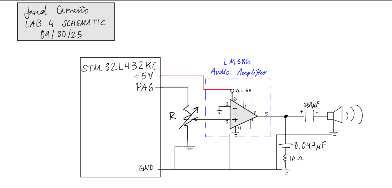
Using an LM386 audio amplifier, the signal was amplified and could be controlled using a potentiometer. As shown in Figure 4, a circuit provided in amp’s datasheet is utilized in order to successfully amplify and control the volume of the signal
Results and Discussion
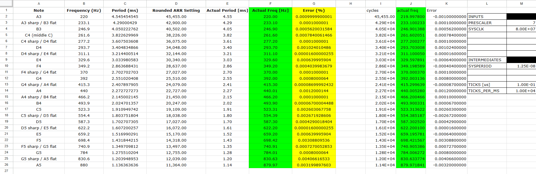
The MCU was able to produce the correct frequencies that were provided to it for the exact duration that was specified for each note. While there were no testbenches for this specific lab, the notes and their durations were accurate using the selected values for PSC and ARR, as shown in Figure 5. Debugging here was important, so using Segger’s build and debug mode and forcing the pin to output one specific frequency was definitely very crucial to ensuring correct implementation.
Conclusion
The lab seemed to have no issues and was able to successfully play both Fur Elise and Mary Had a Little Lamb, but is not limited to either. This lab was definitely very difficult due to the abundance of information that had to be absorbed in order to understand what was going on. Now, I feel very able to set up registers and look through the manuals to find the correct information.
AI Prototype Summary
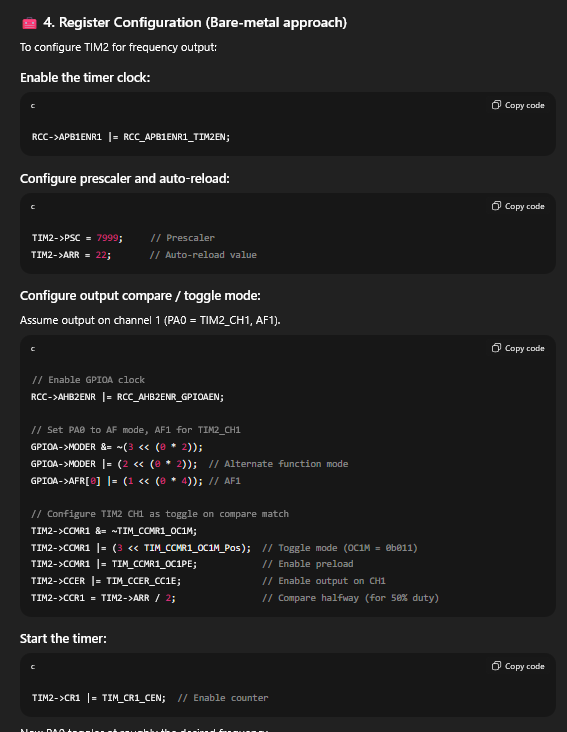
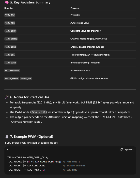
The AI was able to produce a pretty sensible response. I would attribute this to the fact that the information of our STM32 MCU is readily available, along with plenty of examples that the LLM can draw on. I will say that the AI did not mention the EGR register, which is crucial for this implementation to function properly. The LLM’s response is shown below: